Getting Soil Moisture Sensor Information with Android Things and Raspberry Pi 3
PROJECT INFO
Difficulty: Advanced
Estimated time: 2 hours
License: GPL3+
THINGS USED IN THE PROJECT
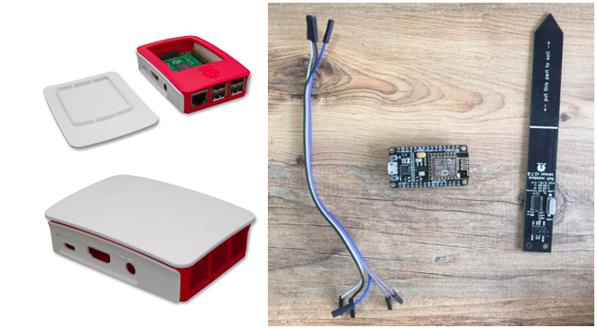
Hardware components:
- NodeMCU ESP8266 Breakout Board x1
- I2C Soil Moisture Sensor x1
- Raspberry Pi3 x 1
- 8 GB SD Card x 1
Software apps and online services:
- Arduino IDE
- IoT-Ignite Service Registration
- AndroidThings Agent Application
- IoT-Ignite Service Application
Hand tools and fabrication machines:
- Soldering iron (optional)
STORY
The project will transfer soil moisture sensor data over wireless through NodeMCU.
This transfer will be done by using an AndroidThings installed gateway.

- NodeMCU will be Wi-Fi Access Point; start transmitting your IP and port number to a network.
- Set Wi-Fi to AP mode, and establish a wireless connection.
- Once the client connection is set; read the frequency of temperature and humidity transmission, and start transmitting the data to the client at this frequency.
- Reconnect to the network if the connection is lost: first close client connection and wait for the re-connection.
- Execute when LED event is happened.
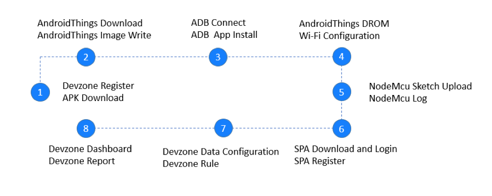
1 Devzone Registeration and Application Download
- Create a free developer account at IoT-Ignite Devzone if you do not have one.
- Login to IoT-Ignite Devzone,
- Download AndroidThings agent,
2 Getting Ready for AndroidThings as IoT Gateway
- Download AndroidThings from this link,
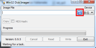
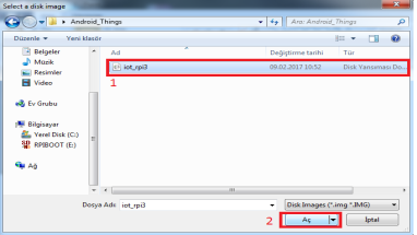
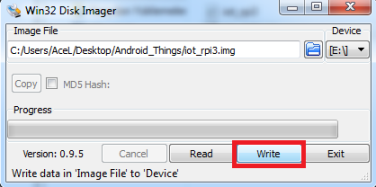
- Download and setup win32 disk imager application,
- Flash the SD Card with AndroidThings Image. Please refer to the following link to learn how to a flash an image.
3 AndroidThings Configuration – Wi-Fi Connection
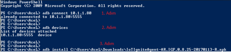
Connect to this IP address using the adb tool:
$ adb connect
 connected to :5555
Raspberry Pi broadcasts the hostname Android.local over Multicast DNS (mDNS). If your host platform supports mDNS, you can also connect to the board using the following command:
$ adb connect Android.local
To connect your board to Wi-Fi using adb:
- Send an intent to the Wi-Fi service that includes the SSID and passcode of your local wireless network:
$ adb shell am startservice \
 -n com.google.wifisetup/.WifiSetupService \
 -a WifiSetupService.Connect \
 -e ssid  \
 -e passphrase
4 AndroidThings Configuration – IoT Agent Installation
- Connect with ADB command,
adb connect device_ip_address
- Download IoT Ignite Agent APK,
- You can use adb to install an APK on an emulator or connected device with the install command:
adb install path_to_apk
5 Prepare NodeMCU for Gateway Registration
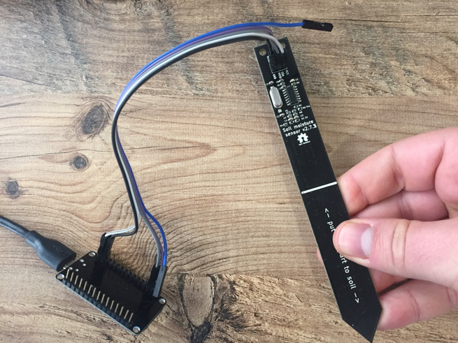
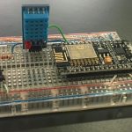
Step 1: Connecting Sensor Component
Thanks for Miceuz
Connect the pins as shown below for device’s physical connection (this connection is configured for the provided sample codes).
The set is physically ready. Now follow the steps to make the set ready for computer installation of the necessary software.
- RED – VCC
- BLUE – GND
- WHITE – SDA – GPIO4 (D2 Pin)
- YELLOW – SCK – GPIO5 (D1 Pin)
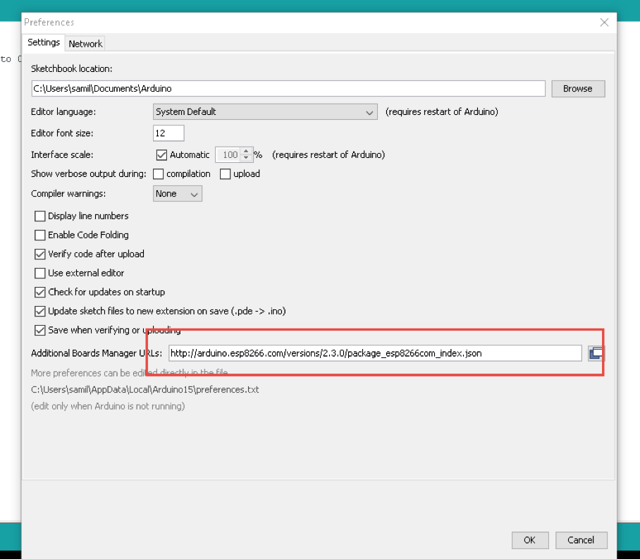
Step 2: Getting Ready for NodeMCU
In Arduino IDE, go to File/Preferences and add additional esp8266 library from the link below to introduce Arduino IDE with NodeMCU to make it programmable.
http://arduino.esp8266.com/versions/2.3.0/package_esp8266com_index.json
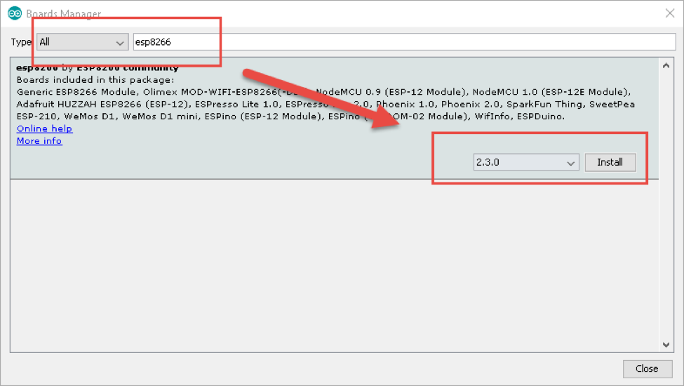
Go to Tool menu and enter esp8266 on board manager screen and click install.
Step 3: Installing File System and Libraries
Your set is ready for installing NodeMCU file system. Download filesystem uploader plugin from https://github.com/esp8266/arduino-esp8266fs-plugin/releases/tag/0.2.0, and extract under Arduino IDE as C:\Program Files (x86)\Arduino\tools\ESP8266FS\tool
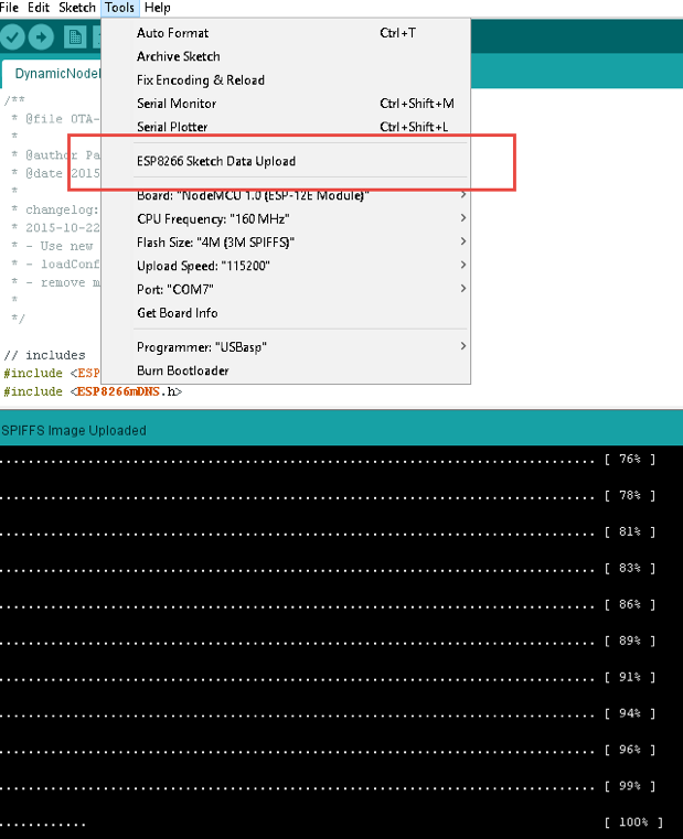
Restart Arduino IDE and make it ready for data upload under Tools menu.
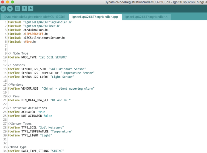
Here we are goint to install the libraries to be used for the application.
You need a simple Arduino Library for the I2C Soil Moisture Sensor version from Chirp. Download and add the file https://github.com/Apollon77/I2CSoilMoistureSensor to IDE.
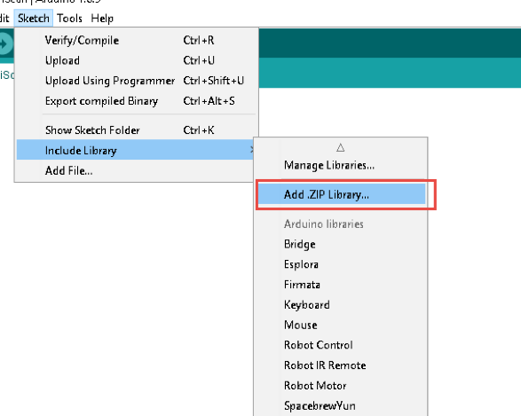
Download timer library from https://github.com/JChristensen/Timer, add this file to IDE by “sketch include the library, add zip library”.
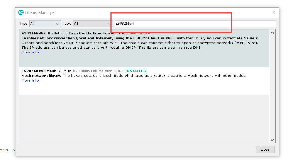
Install other general libraries such as ArduinoJson, ESP8266WiFi, Wire as well (Sketch > Include Library > Manage Library).
Add the program code to Arduino and make sure you have connected the right port to NodeMCU.
Step 5: Generate, Compile, and Upload Code
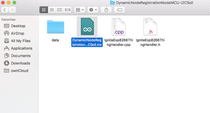
Copy the library within the Github library and extract it in Ardunio IDE, i.e: For Windows, C:\Users\{name}\Documents\Arduino\DynamicNodeRegistrationNodeMCU-IotIgnite
Make sure the data files are under C:\Users\{name}\Documents\Arduino\DynamicNodeRegistrationNodeMCU-IotIgnite\data , and double click file to open.
Now the set is ready with NodeMCU as soon as uploading finishes.
NodeMCU must be an access point when your upload is complete. Now we can register NodeMCU to Gateway with our open source sample application “Service Provider Application”.
6 Service Provider Application and Register NodeMCU for Gateway
When NodeMCU is flashed for the first time, it starts as a server and a Wi-Fi hotspot. Hotspot name starts with “Ignite” prefix. The configuration must include the following parameters:
- NodeID // Customer application registers NodeMCU to IoT Ignite agent with this given unique id. This id should be unique in gateway domain.
- GatewayID // NodeMCU can only be connected to the given gateway id.
- SSID Credentials // Node uses SSID name and password to connect to the local network
Connect your NodeMCU to Wi-Fi and type 192.168.1.4 in your browser. This web page provides wireless and gateway information.
Configured NodeMCU tries to connect to the Wi-Fi network with the given credentials. If an error occurs during Wi-Fi connection, it switches back to hotspot mode. If the connection is successful, it scans for the gateway with the given gateway id. If the maximum number of gateway discovery attempts is reached, it switches back to hotspot mode. The number of maximum attempts is 30 by default.
When it discovers gateway, it sends node inventory to customer application and waits for data configuration.
7 Devzone Data Configuration – Devzone Rule
When your NodeMCU gets registered, it is time to configure for data configuration. Login your Devzone panel;
Click Developments menu item then select Nodes item.
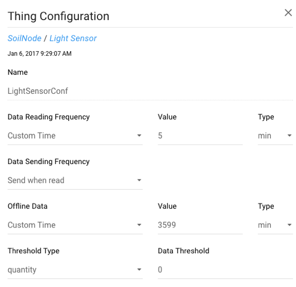
Data configuration provides options for NodeMCU;
- Data Reading Frequency
- Data Sending Frequency
- Threshold Type
- Offline Data
- Custom Configuration
Our example data reading and sending frequency type must be custom and the minimum value is 5 minutes. Set the values. This configuration must be pushed to device every time you change.
Finally, IoT-Ignite will collect data from sensors according to the provided data configuration.
8 Play Time: Devzone Dashboard – Report
Devzone have two visual reporting tools:
- Report Tab
- Dashboard Tab
Report tab is a simple data listing and visualization tool.
Dashboard has an intuitive drag & drop interface. You can edit your own dashboard to display real-time data, interactive virtual actuators in minutes. When you open dashboard you can use various type of dashboard components and you can play configuration options.
There are hidden beauties: Every board operates on a secure, high-performance, enterprise-class cloud system, and every dashboard has a unique URL that you can share.
CODE
GitHub
You can access the project files on GitHub. Click here to access ino files to code on NodeMCU as well as all application source code for Android.
Source Code:
NodeMCU: https://github.com/IoT-Ignite/arduino-sketch-i2c-soil-and-moisture-sensor-example
Arduino ESP8266 filesystem uploader plugin: https://github.com/esp8266/arduino-esp8266fs-plugin
AndroidThings Agent: https://download.iot-ignite.com/AgentApp/


Leave a Reply
Want to join the discussion?Feel free to contribute!